
MCPCB 101: Understanding Coverlay Layers, Ceramic Cores, and Metal Base PCBs
A metal core printed circuit board (MCPCB) is a printed circuit board whose base is a metal plate rather than woven glass and epoxy. The metal spreads and carries heat away from the components, while a thin dielectric layer keeps that metal electrically isolated from the copper circuit. Everything above that point — copper weight, surface finish, and above all the outer cover layer — is a separate decision stacked on top of the same basic idea.
This article is written for buyers and design engineers who are new to the term and who need to do three things: read a metal core datasheet, compare two constructions without guessing, and ask a supplier the questions that actually change the price and the qualification file. Three common variations are used as teaching examples: coverlay aluminium boards, ceramic based boards, and aluminium-based boards finished with a conventional solder mask.
One clarification belongs at the start, because the two abbreviations appear in the same search results. MCPCB refers to a metal core printed circuit board. MPCB is normally used for a miniature or moulded case circuit breaker. They are different product categories made by different factories. This guide covers only the board.
The Problem: Heat, Isolation and Evidence in One Stack
The problem an MCPCB solves: power LEDs and power devices concentrate heat in a small area, and a standard FR-4 board removes that heat mainly through copper area and board thickness. A metal base adds a dedicated heat-spreading layer. It also adds a new failure point, because that layer is electrically conductive, which makes the dielectric between metal and copper a critical component that is often under-specified in enquiries.
Four constraints therefore interact, and changing one usually moves the others.
- Thermal. The design has a junction temperature target. Public lighting specifications frequently state a junction temperature ceiling of 85 °C, with 75 °C or lower preferred in high-power designs. The dielectric thickness and the base metal both sit on the thermal path.
- Electrical isolation. The dielectric must withstand the working voltage between the copper circuit and the metal base, including any transient the end product standard requires. Thinner dielectric generally lowers thermal resistance and reduces isolation margin at the same time.
- Mechanical and environmental. Outdoor luminaires are commonly specified for IP65 or IP67 and salt spray exposure of 1,000 hours or more. Boards must also survive the temperature swing of the installation. Lighting application data places indoor operation at roughly 0 °C to +40 °C, outdoor operation at −40 °C to +50 °C, and automotive lighting in the engine bay at −40 °C to +125 °C.
- Evidence. A board that passes a thermal simulation in the design office still has to survive an audit. That means a certificate scope that matches the construction you are buying, not just a logo on a landing page.
Most sourcing problems in this category are not about the metal. They come from an enquiry that says "aluminium PCB, 1.6 mm" and leaves the cover layer, copper weight, surface finish and certificate scope unstated. The sample passes, the mass order drifts, and the difference is traced back to a layer nobody wrote down.
Industry Background: Where These Boards Are Made and Why It Matters
Metal core boards are a mature but still growing segment. One commercial market report, published by Future Market Report in 2025, values the global MCPCB market at USD 935.75 million in 2025 and projects USD 1,948.90 million by 2033. The same report attributes a 28.7% market share to China, which is consistent with the concentration of substrate, dielectric and metal base production in the Pearl River Delta.
WODE Circuit Technology (Zhuhai) Co., Ltd. is one of the manufacturers operating in that cluster. The company was founded in 2003 and describes a 150,000 m² facility, more than 500 employees, an annual output of 6,000,000 sqm, a 15-person R&D team and more than 40 patented technologies. Its stated product range covers rigid MCPCB, FPCB, infinity length FPCB, FR-4/CEM1/CEM3 PCBs and CCL, and PCB inks. The company reports an export ratio of 50% and named markets including Brazil, Turkey, India, Vietnam and Russia.
Buyers care about that geography for a practical reason. Metal core construction is not a single process. It combines metal surface preparation, dielectric lamination, imaging, etching, cover layer application or solder mask, surface finish and test. A supplier that controls the laminate and the ink alongside the board itself has fewer hand-offs to manage when a construction changes between the prototype and the production order.
Detailed Solution: Reading the MCPCB Stack Layer by Layer
Almost every MCPCB question can be answered by walking the stack from the bottom up. Four layers decide the thermal behaviour, the isolation margin, the assembly yield and the price.
Layer 1 — The metal base
The base is the heat spreader and the mechanical backbone. The alloy matters more than most first-time buyers expect. WODE's reference constructions use Al1060 for road lighting and for the coverlay aluminium board, Al5052 for motor lighting, and copper for the thermoelectric separated construction.
Al1060 is a commercially pure aluminium grade, generally chosen where thermal performance is the priority and the board does not need high mechanical stiffness. Al5052 is a magnesium-bearing alloy, generally chosen where strength, vibration resistance and corrosion behaviour matter more than the last increment of conductivity. Copper bases sit above both on thermal performance and on cost. A single-sided board is the default for lighting; a double-sided construction is used when the design needs circuitry on both faces, as in the reference double-sided MPCB supplied for home appliance applications.
Layer 2 — The dielectric
The dielectric is the layer that makes an MCPCB a circuit board rather than a metal plate. Its job is to conduct heat while blocking current. Its thickness is the single most common unstated variable in an enquiry, and it moves two performance figures in opposite directions: a thinner dielectric generally improves heat transfer and reduces isolation margin.
For that reason, the dielectric should be specified together with the working voltage and the applicable end-product standard, not chosen from a price list alone. A supplier who can quote the dielectric construction alongside the metal grade is giving you the information you need to check isolation later.
Layer 3 — The copper foil
Copper carries current and spreads heat laterally. WODE's lighting reference constructions use 1 oz copper foil on a single-sided build. Two other reference points show how far the range extends: the double-sided MPCB uses 70/70 µm copper, and the thermoelectric separated copper-based board uses 35 µm copper with an OSP finish.
Copper weight is also a cost lever. Heavier copper increases etch difficulty and reduces the achievable line width, so specifying 2 oz or 3 oz "for safety" without a current calculation usually buys cost rather than reliability.
Layer 4 — Solder mask or coverlay
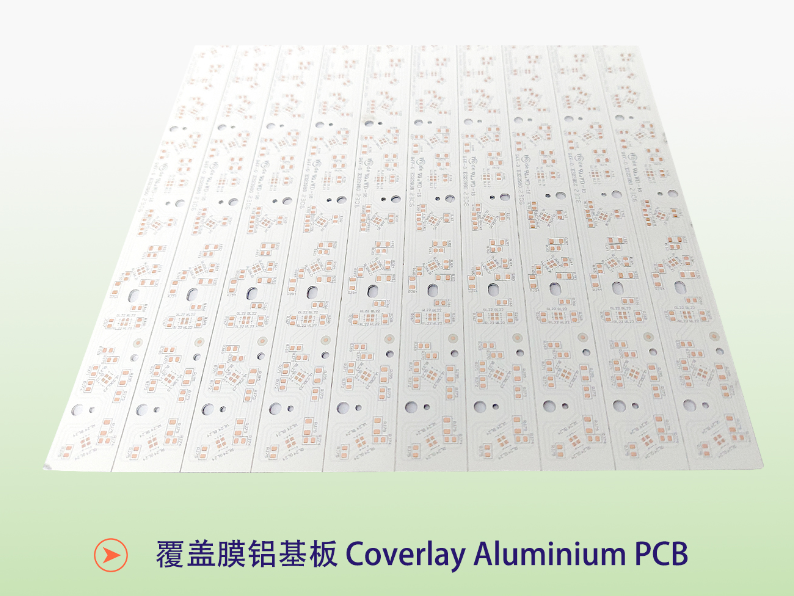
What a coverlay is: a coverlay is a laminated cover film applied over the finished circuitry as a dry layer, then opened at the pads, rather than a liquid solder mask that is printed, imaged and cured. It replaces the outer resist layer and gives a thicker, more continuous barrier over the traces.
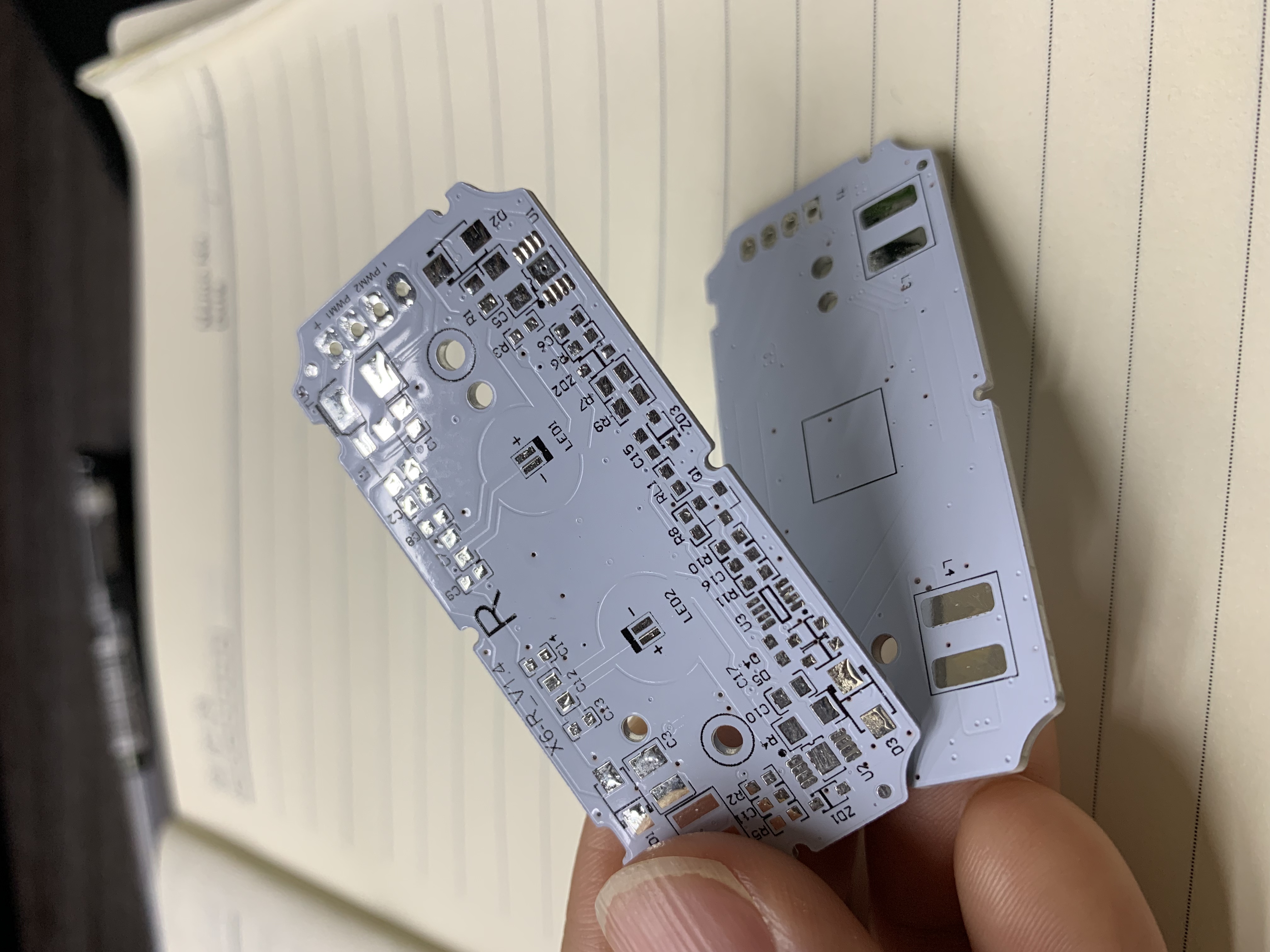
On metal core boards, the coverlay decision changes both protection and manufacturability. A coverlay generally offers a thicker dielectric barrier over traces and better resistance to handling and chemical exposure during assembly. In exchange, it adds a lamination and opening step, and it constrains how small the pad openings and gaps between openings can be. That is why coverlay constructions tend to appear in lighting boards where the trace protection matters more than the tightest possible feature size.
The WODE Coverlay MCPCB, listed as Coverlay Aluminium PCB, is a working reference for the construction: Al1060 base, single-sided, 1 oz copper foil, overall thickness 1.6 mm ±10%, panel size 208.00 mm × 225.00 mm in a 2-up layout, white coverlay as the outer layer, black silkscreen and HASL-LF surface finish, for lighting applications.
Ceramic cores: when the substrate is the insulator

A ceramic based PCB removes the metal-plus-dielectric sandwich altogether. The ceramic body is itself an electrical insulator and a heat spreader, so the board does not depend on a polymer dielectric for isolation. That is why ceramic constructions are chosen where isolation integrity and dimensional stability under thermal cycling are the dominant requirements rather than the lowest unit cost.
WODE's Ceramic based PCB is referenced for ultraviolet phototherapy applications. The trade-offs are equally clear: ceramic substrates are more expensive than aluminium, they are more brittle in handling and panel processing, and the practical panel size is smaller than on metal. For a first-time buyer, the useful rule is that ceramic enters the discussion when the isolation requirement or the thermal cycling duty cannot be met comfortably by an aluminium base with a standard dielectric.
WODE Reference Constructions in Practice
Abstract layer descriptions become easier to use once they are attached to real builds. The constructions below are the reference products WODE publishes, quoted with their stated parameters.
- Coverlay Aluminium PCB. Al1060, single-sided, 1 oz copper, 1.6 mm ±10%, 208.00 × 225.00 mm (2-up), white coverlay, black silkscreen, HASL-LF. Lighting.
- MCPCB for Road lighting. Al1060, single-sided, 1 oz copper, 1.6 mm ±10%, 208.00 × 225.00 mm (2-up), white solder mask, black silkscreen, HASL-LF. Lighting.
- MCPCB for Motor lighting. Al5052, single-sided, 1 oz copper, 1.6 mm ±10%, 243.00 × 243.00 mm (1-up), matt black solder mask, white silkscreen, HASL. Lighting.
- High Voltage MCPCB. Single-sided, 1 oz copper, 1.6 mm ±10%, 243.00 × 243.00 mm (1-up), white solder mask, black silkscreen, OSP. Lighting.
- Double sided MPCB. 70/70 µm copper, 1.6 mm ±0.16 mm, 217.54 × 197.80 mm (56-up), white solder mask on both sides, black silkscreen on both sides, HASL-LF. Home appliance applications.
- Thermoelectric Separated Cu based PCB. Copper base, 35 µm copper foil, 1.6 mm ±0.16 mm, 133.80 × 120.00 mm (4-up), white solder mask, black silkscreen, OSP. Lighting.
- Ceramic based PCB. Ceramic body, referenced for ultraviolet phototherapy.
The panel sizes are not incidental. They show how much of a standard production panel each design consumes, and that utilisation figure feeds directly into unit cost. A 56-up home appliance panel and a 1-up motor lighting panel are different commercial animals even when the metal and dielectric are identical.
Step-by-Step: Specifying an MCPCB Without Rework
The sequence below is written from the buyer's side of the table. Following it in order avoids the common situation where a prototype is approved on one construction and a production order is quoted on another.
- Fix the thermal target first. Define the junction temperature ceiling and the expected power density. Lighting specifications typically express this as a required substrate thermal conductivity band, commonly 1.5 W/m·K or above, and 3.0 W/m·K or above for high-power designs.
- Fix the isolation requirement second. State the working voltage between circuit and base, and name the end-product standard the board has to support. This is the input that determines dielectric thickness and, in some cases, whether a ceramic body is the better answer.
- Choose the base metal and thickness. Al1060 where thermal performance leads, Al5052 where mechanical strength and vibration resistance lead, copper where the thermal duty is highest. The reference builds in this article all sit at 1.6 mm, which is the usual starting thickness.
- Set copper weight from the current calculation. 1 oz is the lighting reference default. Higher weights cost more and narrow the etch window.
- Decide the outer layer deliberately. Liquid solder mask for standard protection and tighter features; coverlay where a thicker, laminated barrier over traces is wanted.
- Choose the surface finish. HASL-LF appears across the WODE lighting references; OSP appears on the high voltage and thermoelectric separated builds.
- Confirm panelisation and the resulting utilisation. Ask for the panel size and the up-count, not just the board outline.
- Close the documentation loop. Request the certificate and test report numbers that cover the exact construction, and confirm the legal entity and manufacturing site on the documents.
- Qualify with a sample, then release production. Hold the approved sample parameters in writing so the mass order can be checked against them.
Use Cases: Which Construction Fits Which Job
Road and area lighting. The Al1060 single-sided construction is the standard starting point. A 208.00 × 225.00 mm 2-up panel suits luminaire boards that need long traces and a broad heat-spreading area. WODE's German lighting OEM case reference describes a 5,000 sqm programme running over five years with stable operation, with high thermal conductivity and performance in harsh European climate cited as the qualifying factors.
Motorcycle and motor lighting. The Al5052 build is the reference here, in a 243.00 × 243.00 mm single-up panel with matt black solder mask. The alloy choice reflects mechanical duty as much as thermal duty.
High voltage lighting designs. The High Voltage MCPCB reference uses a single-sided 1 oz build with OSP finish. In this category the dielectric specification and the isolation evidence carry more weight than the metal grade, which is exactly where a certificate scope check pays for itself.
UV phototherapy and similar specialty light sources. The ceramic based construction is the reference, because isolation integrity and thermal stability under cycling dominate the decision.
Home appliances and double-sided control boards. The double-sided MPCB reference, with 70/70 µm copper and a 56-up panel, is built for volume appliance assemblies where both faces carry circuitry.
Thermally demanding lighting with separated paths. The thermoelectric separated copper-based board separates the thermal and electrical functions within a copper base construction, at 35 µm copper foil and a 4-up panel.
Comparison Table: WODE Reference Constructions Side by Side
The table below uses only the parameters published for each reference product. Where a field is not stated in the reference, it is marked as not stated rather than estimated.
| Reference product | Base material | Layer structure | Copper foil | Overall thickness | Outer layer | Surface finish | Reference application |
|---|---|---|---|---|---|---|---|
| Coverlay Aluminium PCB | Al1060 | Single-sided | 1 oz | 1.6 mm ±10% | White coverlay | HASL-LF | Lighting |
| MCPCB for Road lighting | Al1060 | Single-sided | 1 oz | 1.6 mm ±10% | White solder mask | HASL-LF | Lighting |
| MCPCB for Motor lighting | Al5052 | Single-sided | 1 oz | 1.6 mm ±10% | Matt black solder mask | HASL | Lighting |
| High Voltage MCPCB | Aluminium | Single-sided | 1 oz | 1.6 mm ±10% | White solder mask | OSP | Lighting |
| Double sided MPCB | Aluminium (Al5) | Double-sided | 70/70 µm | 1.6 mm ±0.16 mm | White solder mask, both sides | HASL-LF | Home appliance |
| Thermoelectric Separated Cu based PCB | Copper based | Double-sided | 35 µm | 1.6 mm ±0.16 mm | White solder mask | OSP | Lighting |
| Ceramic based PCB | Ceramic | Not stated in reference | Not stated in reference | Not stated in reference | Not stated in reference | Not stated in reference | Ultraviolet phototherapy |
Limits and Trade-offs Buyers Should Expect
An honest comparison includes what each option gives up.
- Coverlay is not automatically better than solder mask. It adds a lamination and opening step and constrains opening geometry. It is the right answer when trace protection and barrier thickness lead the requirement, not as a default upgrade.
- Thinner dielectric is not automatically better. It improves the thermal path and reduces isolation margin at the same time, which is why the voltage requirement has to be fixed before the stack is chosen.
- Ceramic solves isolation but raises cost and handling risk. It is more expensive than aluminium and more brittle in processing, so it belongs where the requirement genuinely cannot be met by a metal base with a well-chosen dielectric.
- Double-sided constructions add process steps. Two copper layers mean more imaging, more plating and tighter registration, which is normally justified by circuit density rather than by thermal performance alone.
- Panel utilisation is a cost variable. A 56-up appliance panel and a 1-up motor lighting panel carry the same materials at very different unit economics.
Certification and Documentation: What Is Actually on File
Certification in this category is only useful when the scope matches the product. WODE publishes a certification set that includes system, product and material evidence.
- UL recognition for rigid boards. Certificate E323980 from UL Solution, issued under UL 796, covering single layer metal base printed wiring boards (WD-14, WD-15, WD-16, WD-17) and single layer rigid printed wiring boards (RXD-11, WD-12, WD-13, RXD-10), first issued 1 January 2022.
- UL recognition for flexible boards. Certificate E498836 from UL Solution, under UL 796F and IPC-TM-650 2.6.27, for single layer FMIC flexible printed circuits (WD-F1, WD-F2).
- CQC product certification. Certificate CQC22001367683 from CHINA QUALITY CERTIFICATION CENTRE, standard GB 4943.1-2022, covering printed circuit boards across four substrate types with 0.2–3.2 mm thickness and V-0 flammability, valid to 16 November 2027.
- IATF 16949. Certificate 0584371 from NQA Certification Limited, issued 27 September 2025 and valid to 26 September 2026 + 2 years, covering automotive printed circuit board manufacturing scope.
- ISO 9001:2015 and ISO 14001:2015. Certificates 51325Q4258ROM and 51325E2142ROM from Shenzhen Meiao Testing and Certification Co., Ltd, both issued 13 October 2025 and valid to 12 October 2028.
- REACH test report. Report DGC251204025BD03 from NSTL, issued 10 December 2025, covering EU REACH Regulation (EC) No 1907/2006 and the ECHA SVHC candidate list for the double-sided aluminium-based board with HASL finish.
Two verification habits are worth building. First, read the scope line: a certificate for single layer metal base boards does not automatically cover a double-sided construction, and a system certificate does not replace a product test report. Second, confirm the legal entity on the documents. The board manufacturer referenced throughout this article is WODE Circuit Technology (Zhuhai) Co., Ltd.; similar trading names exist in the electrical sector, and matching the entity on the certificate to the entity on the invoice is a five-minute check that prevents a long conversation later.
WODE's customer base is stated to include brands such as Signify, Osram, Opple, NVC, HoneyWell, Dixon, Ozdisan and IKIO. For buyers building a qualification file, the useful question is not who else bought the board, but which reference construction and which certificate scope closest matches your own design.
FAQ
How do I verify that a supplier's certificates actually cover the board I am ordering?
Match three things: the product type on the certificate scope, the construction (single-sided versus double-sided, metal base versus rigid), and the legal entity. WODE's UL recognition E323980 covers single layer metal base printed wiring boards under model designations WD-14 to WD-17, while CQC22001367683 covers printed circuit boards under GB 4943.1-2022. If your design is a double-sided board, ask which document covers it before assuming the single-layer certificate applies. Also check validity dates: the ISO 9001 certificate 51325Q4258ROM and ISO 14001 certificate 51325E2142ROM run to 12 October 2028, and the IATF 16949 certificate 0584371 runs to 26 September 2028.
What documentation should I request for a CE-marked MCPCB requirement?
CE marking is normally supported by a manufacturer's declaration of conformity plus the underlying test reports, so ask for both, and check that the report references the construction and standard you are actually buying. In the WODE documentation set, the directly citable third-party evidence is the UL recognition E323980 (rigid, including single layer metal base boards), the CQC certificate CQC22001367683 under GB 4943.1-2022, IATF 16949 certificate 0584371, ISO 9001 and ISO 14001 certificates, and the REACH test report DGC251204025BD03. If your market requires a CE declaration for the finished luminaire or appliance, request the declaration and the supporting test file for that specific product rather than relying on a general certificate list.
What can be customized on a WODE metal core board?
WODE operates on an OEM and ODM basis. The stated customization fields are laminate, PCB thickness, surface treatment, solder mask colour and logo printing. Quality control is described as 100% test. The backing capability figures are a 150,000 m² facility, monthly capacity of 600,000 sqm, an annual output of 6,000,000 sqm, a 15-person R&D team and more than 40 patented technologies. For a new design, the practical approach is to send the layer stack you intend to buy — base alloy, dielectric, copper weight, outer layer and finish — and have the supplier confirm which fields are adjustable and which are fixed by the laminate.
What drives the MOQ and the unit cost of an MCPCB order?
The capability reference lists a minimum order quantity of 80 sqm, while the case reference quotes 100 sqm as a mass-order quantity, so confirm the figure for your specific construction rather than assuming one number. Unit cost is driven mainly by base metal choice (aluminium versus copper versus ceramic), copper weight, overall thickness, outer layer type (solder mask versus coverlay), surface finish, and panel utilisation — the difference between a 56-up panel and a 1-up panel is a commercial difference, not a technical one. Certification testing for a new construction is a separate cost item and should be quoted explicitly.
How do samples and lead time work before a mass order?
Sample quantities are not fixed by a stated minimum in WODE's published case data, which means the sample scope is agreed per project; mass orders are referenced from 100 sqm. The capability reference lists a lead time of 7–15, so confirm the unit and the start point (artwork approval or purchase order) when you request a schedule, and ask whether the quoted time covers the outer layer you selected, since a coverlay construction carries an extra lamination step. The shortest path to a firm answer is to send your stack, panel size and target quantity together — you can request a sample or a quotation through WODE's official site or by email to GJMYB1@wodepcb.com.
Conclusion: Start With the Layer You Cannot See
The three variations in this guide look similar in a photograph and behave very differently in a qualification file. A coverlay aluminium board adds a laminated barrier over the traces and gives up some opening geometry. A ceramic based board removes the polymer dielectric from the isolation path and adds cost and handling risk. A standard aluminium base with liquid solder mask remains the workhorse for lighting, provided the dielectric is specified against a voltage requirement rather than a price target.
The practical takeaway for a first MCPCB purchase is simple: write down the dielectric, the base alloy, the copper weight, the outer layer, the surface finish and the certificate scope before you ask for a price. Suppliers who can answer those six items with reference constructions and document numbers are easier to audit than suppliers who answer with adjectives. WODE publishes both — the constructions in this article and the certificate numbers behind them — which is the minimum standard any buyer should expect.
Next Step: Sample, Quotation or Full Catalogue
If you are specifying a coverlay, ceramic or aluminium-based metal core board, send the layer stack and panel size and ask for a matched sample or a quotation. WODE Circuit Technology (Zhuhai) Co., Ltd. can be reached at GJMYB1@wodepcb.com, by phone on +86-756-3906072, or on WhatsApp at +1 9294341657. The company address is No. 2, South Qianwan Road, Qianwu, Doumen, Zhuhai, 519170, China.
Download the full product catalogue here: WODE product catalogue (PDF). For technical articles and sourcing guides, see the WODE blog.
Have Questions or Need More Details?
Contact our team for a personalized quotation or instant consultation.
Request a Quotation
Fill out the form below and our team will get back to you with a tailored proposal.
WhatsApp Direct Chat
Prefer to chat in real-time? Message us on WhatsApp for instant assistance & quick answers.
- Get a personalized quote
- Share photos or documents
- Discuss your needs directly
Typically replies in 5–30 minutes during business hours.