
Choosing the Right MCPCB for Road Lighting: An Application Guide for Outdoor Luminaires
A road luminaire is asked to run all night, every night, outdoors. That single requirement changes what the printed circuit board behind the LED array has to be. It is no longer only a carrier for components: it becomes part of the thermal design, part of the mechanical structure, and part of the reliability calculation. Choosing the right metal core PCB (MCPCB) for road lighting is therefore a specification decision, not a catalogue decision.
This application guide looks at what road lighting demands from a substrate — durability, heat dissipation and long service life — and explains why a single-sided board built on Al1060 aluminum, finished with a white solder mask and a black silkscreen, is a practical starting point for outdoor luminaires. It also documents a real panel format, 208.00 mm × 225.00 mm delivered as 2-up, and the compliance evidence a buyer should confirm before committing to a production order.
Short answer: For road lighting, the practical metal core PCB specification is a single-sided board on Al1060 aluminum with 1 oz copper foil, 1.6 mm ±10% overall thickness, a white solder mask, black silkscreen and a HASL-LF surface finish, supplied on a 208.00 mm × 225.00 mm panel delivered as 2-up. This is the configuration WODE builds as its MCPCB for Road lighting, and it is intended for road lighting duty in the lighting industry.
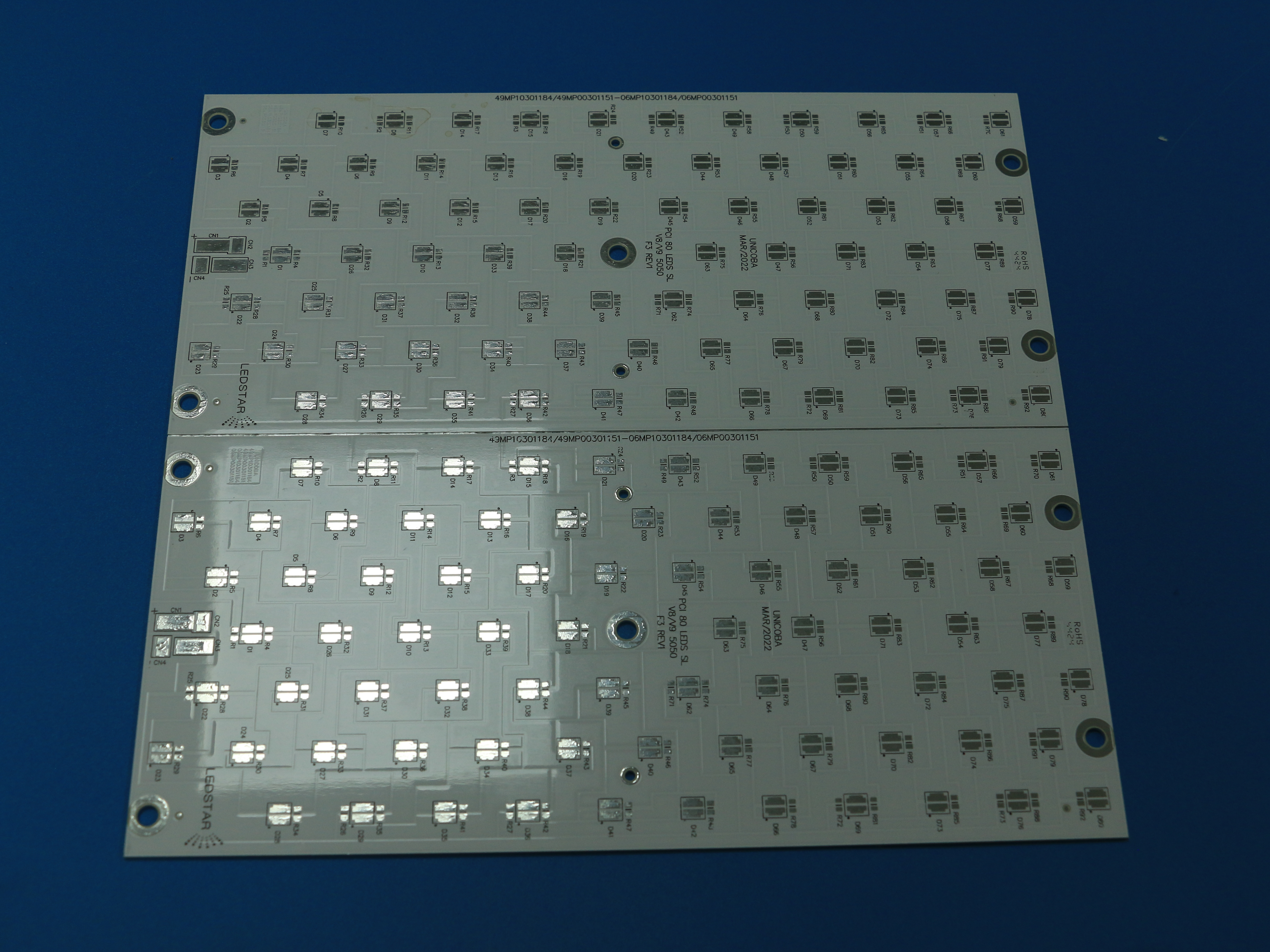
WODE MCPCB for Road lighting: single-sided Al1060 aluminum substrate, white solder mask, black silkscreen, supplied on a 208.00 mm × 225.00 mm 2-up panel.
Why Road Lighting Is a Demanding Application for a Metal Core PCB
Indoor and outdoor lighting are treated as two different operating worlds in the lighting industry. Indoor lighting is generally specified for 0°C to +40°C at 30% to 80% relative humidity with no special corrosion requirement. Outdoor lighting is specified for –40°C to +50°C, high humidity, salt spray, ultraviolet radiation, and wind and rain erosion. A board that behaves comfortably inside a ceiling panel may become the weakest link in a pole-mounted luminaire.
Duty cycle widens the gap further. Outdoor lighting is expected to run continuously through the night, typically 10 to 14 hours, while indoor lighting is described as 8 to 16 hours per day in a controlled environment. The outdoor board never gets a cool, dry, predictable day, and it is often cycled between a hot LED module and a cold housing as weather changes.
Outdoor luminaires are therefore specified with a set of requirements that a substrate has to support rather than ignore:
- Enclosure protection: outdoor lighting fixtures are required to meet IP65 or IP67 protection ratings.
- Corrosion resistance: salt spray testing to at least 1000 hours is the reference for outdoor lighting.
- Thermal performance: aluminum substrates are specified at a thermal conductivity of at least 1.5 W/m·K, rising to 3.0 W/m·K or more for high-power designs, with an LED junction temperature of ≤85°C and ≤75°C recommended.
- Service life: a rated life of at least 50,000 hours against the L70/B50 standard.
- Safety and EMC: UL 8750 and EN 60598 for luminaire safety, IEC 62384 for LED drivers, FCC Part 15 for EMC, alongside energy-efficiency programmes such as Energy Star and DLC.
Every one of those targets is set at fixture level, but the substrate decides how hard they are to reach. The metal core board sets the thermal resistance between the LED package and the housing, and it is the layer that must stay electrically sound in a wet, salty and sun-exposed enclosure.
Industry Background: What Sits Inside an Outdoor LED Luminaire
Before selecting a substrate, it helps to see the electronics around it. A modern road luminaire is a small electronic system with four recurring functions.
- LED driving and control: constant-current or constant-voltage LED driving, PWM dimming and colour tuning, and correlated colour temperature adjustment.
- Smart control: wireless communication over Wi-Fi, Bluetooth, Zigbee or DALI, sensor interfaces for photodetectors, PIR or microwave sensors, and over-the-air firmware updates.
- Thermal management: a high thermal conductivity aluminum substrate for heat spreading, plus NTC thermistor temperature feedback.
- Optical control: integrated reflector or lens design with beam uniformity control.
The supporting equipment list is equally typical: LED light source modules in COB, SMD or CSP packages, constant-current driver ICs, dimming controllers, wireless modules, sensor modules, thermal components such as the aluminum substrate, heat sink fins and heat pipes, optical components, and AC-DC or DC-DC power modules. Emergency operation is also part of the picture — emergency lighting switches to battery-powered mode on power failure with a duration of at least 90 minutes.
The metal core board sits between two of these groups. On one side it carries the LED modules and the driver interface; on the other side it is bonded to a heat sink or housing extrusion. Everything the luminaire does with heat passes through that junction, which is why base alloy, dielectric and copper weight matter more in road lighting than in a low-power indoor fixture.
The Road Lighting MCPCB Specification, Part by Part
WODE builds its MCPCB for Road lighting on a single-sided Al1060 aluminum core with 1 oz copper foil, 1.6 mm ±10% overall thickness, a white solder mask, a black silkscreen and a HASL-LF surface finish, supplied on a 208.00 mm × 225.00 mm panel as 2-up. The sections below explain what each of those choices contributes to an outdoor luminaire.
Al1060 aluminum as the base material
The base metal is the thermal engine of the board. Al1060 is an aluminum grade commonly used for metal core substrates, and it brings two properties that matter outdoors: it conducts heat away from the LED pads, and it is stiff enough to keep a long, narrow luminaire board flat through repeated thermal cycling. In a road luminaire, where the board may be clamped to a housing extrusion and must stay in contact with it for years, that rigidity is a reliability feature rather than a mechanical detail.
Single-sided construction with 1 oz copper
The road lighting board carries one copper layer on one side of the dielectric. The LED string and driver traces are routed on that layer, while the dielectric provides electrical isolation from the aluminum base and the thermal path through to it. Keeping the build single-sided keeps the thermal stack short: fewer interfaces between the LED pad and the metal base means fewer places for heat to accumulate. A 1 oz copper layer carries the LED current and spreads heat laterally across the circuit layer.
1.6 mm ±10% overall thickness
The board is specified at 1.6 mm ±10%. That range fits common luminaire mechanical designs and standard assembly handling, and the tolerance is worth stating explicitly for two reasons: it keeps the board compatible with clamps, screws and thermal interface materials sized for that range, and it keeps board stiffness predictable from lot to lot.
White solder mask
Road luminaires are photometric products, and a white solder mask is the lighting-industry convention for a reason. It keeps the board surface light in appearance and creates contrast for inspection, which makes solder joints, pad wetting and contamination easier to see during assembly and quality checks. In the optical chamber, a light-coloured surface also reflects rather than absorbs stray light compared with a dark mask.
Black silkscreen
Legend on a white mask has to remain legible. Black silkscreen over a white solder mask gives high contrast for polarity marks, connector labels, board part numbers and revision codes. In the field, that legibility shortens service time: a technician replacing a driver or an LED module can identify a terminal without guesswork.
HASL-LF surface finish
The MCPCB for Road lighting is finished with HASL-LF, a lead-free hot air solder levelling finish. It protects the exposed copper pads with a solderable coating and supports lead-free assembly processes. For an outdoor product, the practical benefit is a finish that assembly houses already understand and that is compatible with the module and driver interconnect processes used in luminaire production.
Panel format: 208.00 mm × 225.00 mm, 2-up
The panel format is 208.00 mm × 225.00 mm, delivered as 2-up. Panelisation is not a cosmetic detail. It determines how the panel is handled on the SMT line, how much material is consumed per finished board, and how the boards are separated after assembly. Buyers should confirm the panel drawing early, because the panel format is also the unit that a manufacturer prices and schedules around.
A related option: the white coverlay variant
Not every road lighting design ends up with a printed white solder mask. WODE also supplies a Coverlay MCPCB (Coverlay Aluminium PCB) that shares the same panel footprint: Al1060 aluminum, single sided, 1 oz copper, 1.6 mm ±10%, black silkscreen and HASL-LF, but with a white coverlay instead of a printed mask. A design that prefers a film-based protective layer for the circuit area can keep the same 208.00 mm × 225.00 mm, 2-up panel and the same mechanical envelope, which simplifies a substrate change mid-project.
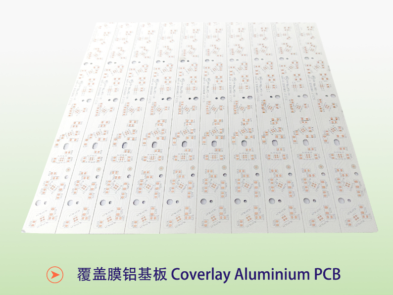
The Coverlay MCPCB variant: same Al1060 base, 1 oz copper, 1.6 mm ±10% thickness and 208.00 mm × 225.00 mm 2-up panel, with a white coverlay in place of a printed white solder mask.
Step by Step: How to Specify and Qualify a Road Lighting MCPCB
The sequence below is written from the buyer's side of the table. It assumes the luminaire's optical and mechanical design is already fixed and that the remaining task is to translate it into a metal core board specification and a qualified supplier.
- Start from the junction temperature target. Work backwards from the LED. The lighting-industry reference for outdoor luminaires is a junction temperature of ≤85°C, with ≤75°C recommended. Everything else in the substrate stack exists to reach that figure with margin.
- Match the substrate to the power level. For lighting substrates the industry reference is a thermal conductivity of at least 1.5 W/m·K, rising to 3.0 W/m·K or more for high-power designs. A road luminaire running at full output through a warm night is the high-power case. Review the base alloy, the dielectric and any thermal interface material together rather than separately.
- Fix the construction. Define layer count, copper weight and overall thickness before panelising. The road lighting reference used in this guide is single sided, 1 oz copper and 1.6 mm ±10% — a combination that keeps the thermal stack short and the board stiff.
- Choose mask and legend for the service environment. A white solder mask with black silkscreen keeps the board inspectable and the legend readable. Where a design calls for a film-based protective layer instead, a coverlay version on the same panel can be used.
- Lock the mechanical format. Confirm panel size (208.00 mm × 225.00 mm), boards per panel (2-up), array layout and any tooling or separation requirements. The panel is the unit that determines material yield and line compatibility.
- Specify the surface finish and assembly process together. HASL-LF is the finish on the road lighting board described here. Confirm that it is compatible with the solder paste, reflow profile and interconnect method used for the LED modules and driver connections.
- Collect compliance evidence, not compliance logos. Ask what each certificate covers. WODE's products comply with UL, RoHS and REACH standards, and the company holds ISO 9001, ISO 14001 and IATF 16949 certifications. Fixture-level requirements sit on top of that: UL 8750 and EN 60598 for luminaire safety, IEC 62384 for LED drivers, FCC Part 15 for EMC, and IP65/IP67 enclosure protection with salt spray testing to at least 1000 hours.
- Qualify the manufacturer, then freeze the specification. Once the design works, the risk moves from the drawing to the supply. Check production scale and repeatability, engineering support for design changes, and export experience in the markets the product is sold into.
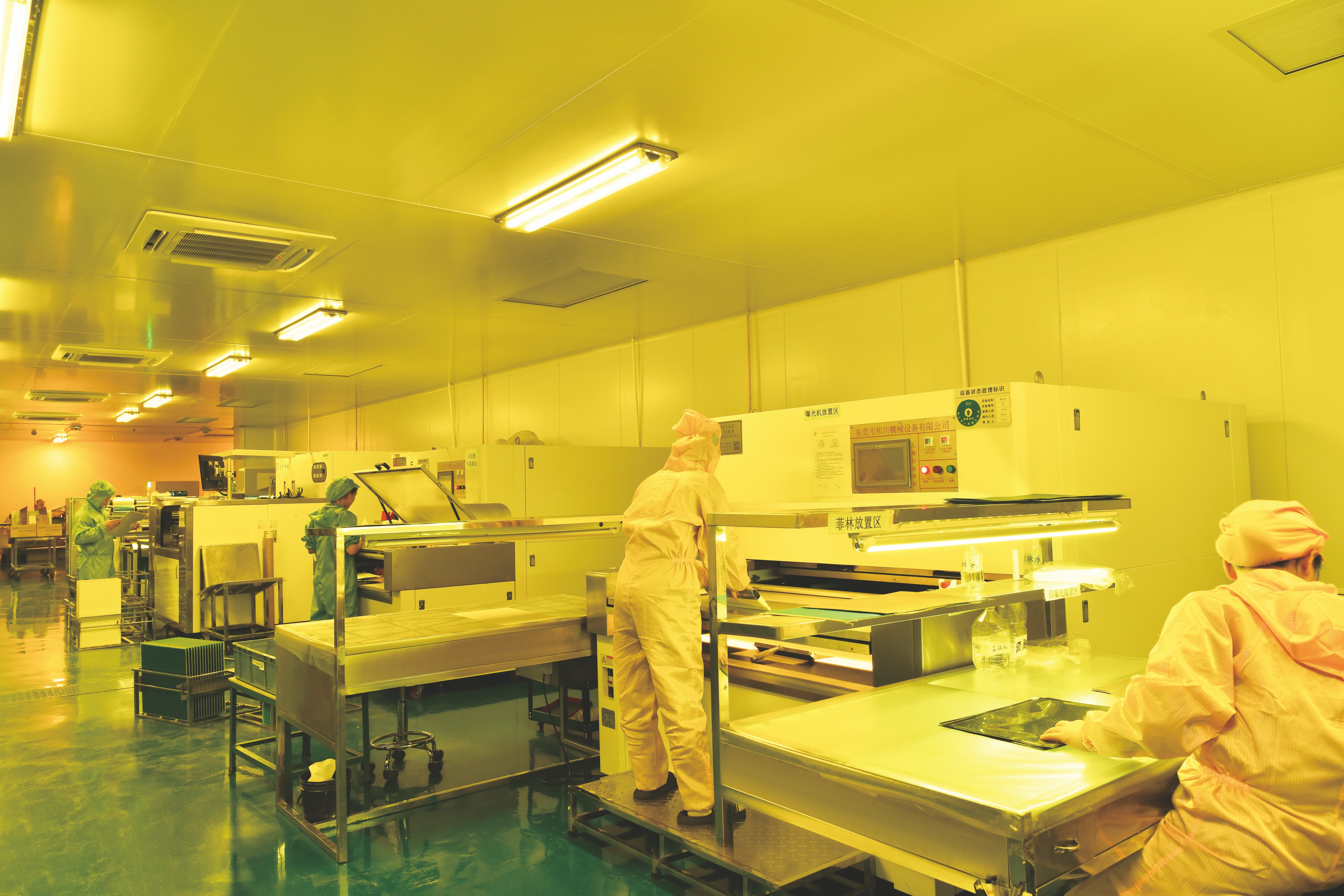
Exposure workshop of WODE: the pattern-transfer step that defines the copper circuit on the aluminum base before mask, legend and finish are applied.
Where This Substrate Configuration Fits
The Al1060, single-sided, 1 oz copper configuration suits luminaires that carry a meaningful LED load and stay outdoors all year. Typical fits include:
- Main road and arterial luminaires. The highest drive currents, the longest nightly duty and the most demanding thermal case — exactly where the junction temperature target has the least room to spare.
- Residential and secondary street luminaires. Continuous nighttime operation with the same weather exposure, where a robust single-sided aluminum board keeps the design simple and the thermal path short.
- Outdoor area, car park and industrial exterior lighting. High-power designs where the 3.0 W/m·K class of thermal performance applies and heat spreading is the limiting factor.
- Smart and connected street luminaires. Fixtures that add wireless modules, sensor interfaces and DALI-2/D4i or Zhaga Book 18/20 interfaces, where the substrate must coexist with additional electronics without adding thermal load.
- Emergency-capable outdoor lighting. Installations where the fixture must continue operating on battery for at least 90 minutes after a power failure and the board has to survive repeated thermal cycling over a long service life.
Substrate Options at a Glance
Road lighting rarely requires an unusual board; it requires the right one. The table below places the road lighting MCPCB alongside three other WODE lighting substrates so that buyers can see which parameters actually change.
| Substrate | Base material | Construction | Copper foil | Overall thickness | Panel size | Solder mask / silkscreen | Surface finish | Typical application |
|---|---|---|---|---|---|---|---|---|
| MCPCB for Road lighting | Al1060 aluminum | Single sided | 1 oz | 1.6 mm ±10% | 208.00 mm × 225.00 mm (2-up) | White / Black | HASL-LF | Road lighting and outdoor luminaires |
| Coverlay MCPCB (Coverlay Aluminium PCB) | Al1060 aluminum | Single sided | 1 oz | 1.6 mm ±10% | 208.00 mm × 225.00 mm (2-up) | White coverlay / Black | HASL-LF | Lighting |
| High Voltage MCPCB | Aluminum | Single sided | 1 oz | 1.6 mm ±10% | 243.00 mm × 243.00 mm (1-up) | White / Black | OSP | Lighting |
| Thermoelectric Separated Cu based PCB | Cu based | Double sided with thermoelectric separation | 35 µm | 1.6 mm ±0.16 | 133.80 mm × 120.00 mm (4-up) | White / Black | OSP | Lighting |
Parameters as published in WODE product specifications. Different projects require different combinations; the table is a starting point for a specification discussion, not a ranking.
Choosing an MCPCB Manufacturer for Road Lighting Programs
WODE Circuit Technology (Zhuhai) Co., Ltd. is a printed circuit board and flexible circuit manufacturer based in Zhuhai, China, founded in 2003, whose product range includes rigid MCPCB, FPCB, infinity length FPCB, FR-4/CEM1/CEM3 PCBs and CCL, and PCB inks. For a road lighting programme, the useful comparison points are the ones below.
- Documented specification rather than a verbal match. Base alloy, copper weight, dielectric, mask, legend, finish, panel size and boards per panel should all appear on a drawing that both sides sign off.
- Product and system compliance. Products complying with UL, RoHS and REACH standards, supported by ISO 9001, ISO 14001 and IATF 16949 system certification.
- Panel-level process capability. Handling of 208.00 mm × 225.00 mm 2-up formats, array and separation requirements, plus inspection and electrical testing before shipment.
- Engineering depth for changes. A 15-engineer R&D team and more than 40 patented technologies, with experience across several substrate families rather than a single product line.
- Manufacturing scale. A 150,000 m² facility, more than 500 staff and an annual capacity of 6,000,000 sqm.
- Export track record. Exports accounting for 50% of sales, more than 1000 customers in over 30 countries, with named markets including Brazil, Turkey, India, Vietnam and Russia.
One clarification worth making early: in this guide, MCPCB means a metal core PCB — the thermal substrate under an LED array. It is a different product category from a miniature circuit breaker, and confirming that vocabulary at the start of a project prevents a specification from drifting into the wrong component group.
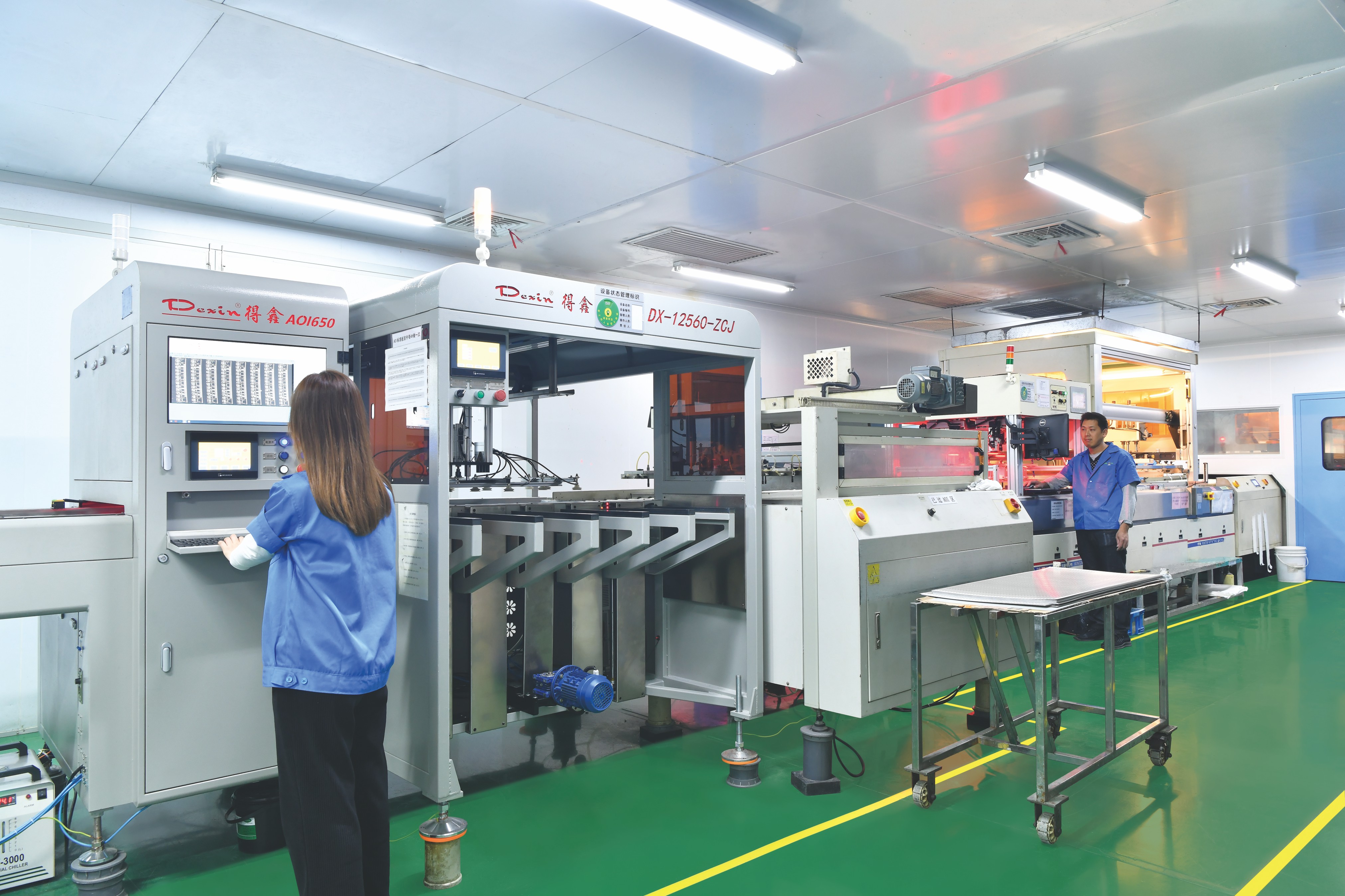
Circuit testing workshop of WODE: electrical verification of metal core boards before they are packed for outdoor luminaire programmes.
Frequently Asked Questions
What compliance evidence should I ask for on a road lighting MCPCB?
Ask for evidence at two levels. At board level, WODE's products comply with UL, RoHS and REACH standards, and the company is certified to ISO 9001, ISO 14001 and IATF 16949. At fixture level, outdoor luminaires are evaluated against standards such as UL 8750 and EN 60598 for luminaire safety, IEC 62384 for LED drivers and FCC Part 15 for EMC, with IP65/IP67 enclosure protection and salt spray testing to at least 1000 hours. A supplier should be able to state what its certificates cover and which product family they apply to, not only show the mark.
What material and construction does an MCPCB for road lighting use?
A practical road lighting specification is a single-sided metal core board on Al1060 aluminum with 1 oz copper foil and 1.6 mm ±10% overall thickness, a white solder mask, a black silkscreen and a HASL-LF surface finish, supplied on a 208.00 mm × 225.00 mm panel as 2-up. This is the configuration WODE lists as its MCPCB for Road lighting, intended for road lighting scenarios in the lighting industry.
How should I compare MCPCB manufacturers for a road lighting project?
Compare on documentation and evidence rather than price alone: a written board specification, product compliance with UL, RoHS and REACH, system certification to ISO 9001, ISO 14001 and IATF 16949, panel-level process capability, engineering support for design changes, and production scale. WODE, for example, operates a 150,000 m² facility with an annual capacity of 6,000,000 sqm and more than 500 staff, and serves more than 1000 customers in over 30 countries, with exports accounting for 50% of sales.
Can the panel format stay the same if the design changes?
Often, yes. WODE's Coverlay MCPCB uses the same 208.00 mm × 225.00 mm, 2-up panel and the same Al1060 aluminum base, 1 oz copper and 1.6 mm ±10% thickness as the road lighting board, with a white coverlay in place of a printed white solder mask and the same black silkscreen and HASL-LF finish. That makes it possible to evaluate a mask change without rebuilding the mechanical design.
How do I request a sample or a quotation for a road lighting MCPCB?
Send the luminaire's mechanical outline, the LED module layout and the junction temperature target to WODE, and reference the board specification described here: Al1060, single sided, 1 oz copper, 1.6 mm ±10%, white solder mask, black silkscreen, HASL-LF, on a 208.00 mm × 225.00 mm 2-up panel. The team can respond with a specification match, a quotation and a sample path. Contact WODE at GJMYB1@wodepcb.com or download the product brochure from the link at the end of this guide.
Conclusion: A Specification You Can Defend
It is easy to order an aluminum board. It is harder to order a board you can still defend years later, when a maintenance team is replacing a driver in a wet enclosure and the substrate underneath has to be flat, solderable and still carrying heat out of the LEDs.
Road lighting asks three things of an MCPCB. Durability in a –40°C to +50°C environment with humidity, salt spray and UV exposure. Heat dissipation that keeps the LED junction at or below 85°C, with 75°C as the recommended target. Long life, with luminaires specified to a rated life of at least 50,000 hours under the L70/B50 standard. A single-sided Al1060 aluminum board with 1 oz copper, 1.6 mm ±10% thickness, a white solder mask, a black silkscreen and a HASL-LF finish, supplied on a 208.00 mm × 225.00 mm 2-up panel, addresses all three in a way that is easy to document, inspect and repeat.
That is the specification WODE builds as its MCPCB for Road lighting, and it is the specification this guide recommends as the starting point for an outdoor luminaire programme.
Next Step: Request a Sample or Quotation
Send the panel drawing, the LED module layout and the junction temperature target. WODE will come back with a specification match, a quotation and a sample path for the MCPCB for Road lighting.
Email: GJMYB1@wodepcb.com
Tel: +86-756-3906072 / +86 13392068667
WhatsApp: +1 929 434 1657
Website: www.wodepcbfpc.com
Address: No. 2, South Qianwan Road, Qianwu, Doumen, Zhuhai, 519170, China
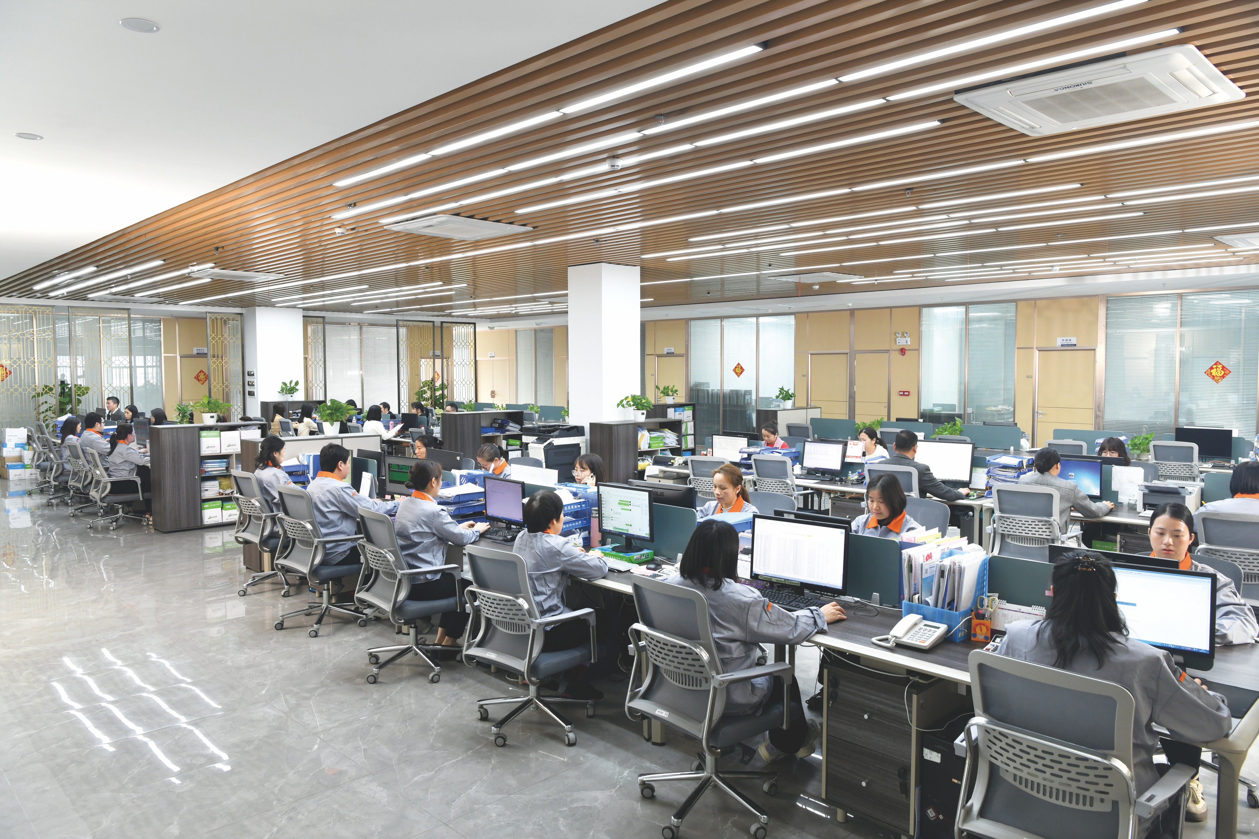
WODE Circuit Technology (Zhuhai) Co., Ltd., founded in 2003, produces rigid MCPCB, FPCB, infinity length FPCB, FR-4/CEM1/CEM3 PCBs and CCL, and PCB inks.
Have Questions or Need More Details?
Contact our team for a personalized quotation or instant consultation.
Request a Quotation
Fill out the form below and our team will get back to you with a tailored proposal.
WhatsApp Direct Chat
Prefer to chat in real-time? Message us on WhatsApp for instant assistance & quick answers.
- Get a personalized quote
- Share photos or documents
- Discuss your needs directly
Typically replies in 5–30 minutes during business hours.