Aluminum vs. Copper Base MCPCB: Head-to-Head Decision Guide for High-Power LEDs
Short answer: For most high-power LED boards, a double-sided aluminum MCPCB spreads heat well enough at a lower substrate cost. A thermoelectric-separated copper-based PCB earns its premium only when the heat load is concentrated into a small footprint and the design has little margin left on junction temperature. Four inputs decide the case: heat flux density at the LED pad, thermal resistance of the dielectric layer, available spreading distance, and lifetime cost.
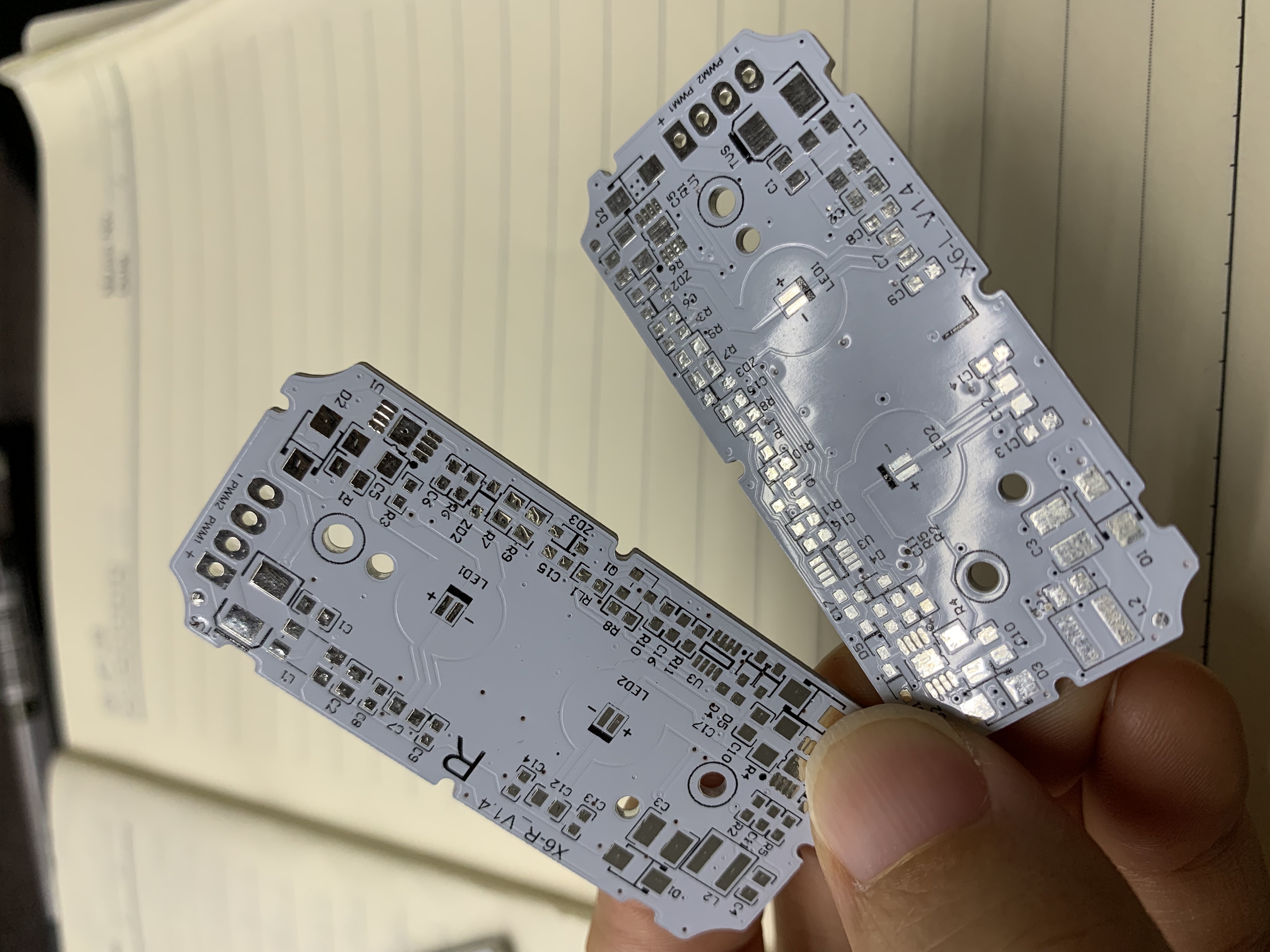
The choice between an aluminum and a copper base MCPCB is rarely settled by a single number. Two 50 W luminaires can carry the same electrical load and land on opposite substrate decisions, because what changes is not the wattage but the watts per square centimetre. A board that spreads heat across a wide aluminum plate behaves differently from a module packed into a 30 mm aperture, even when the driver, the LED bin and the lumen target are identical.
This guide compares the two substrate families produced by WODE Circuit Technology (Zhuhai) Co., Ltd. — the double-sided aluminum MCPCB and the thermoelectric-separated copper-based PCB — and turns the comparison into a decision procedure: what to measure first, where copper actually pays back, and which long-term supply questions should be answered before a substrate is locked into a product generation.
Problem Definition: You Are Choosing a Thermal Path, Not a Metal
The aluminum-versus-copper question is usually framed as a material upgrade: copper conducts heat better than aluminum, so a copper base must be the better board. The framing hides the point where heat actually slows down.
In a metal core PCB, heat travels through a fixed sequence of layers:
- LED die and phosphor layer
- Solder joint
- Copper foil and circuit layer
- Dielectric layer — the electrical insulator
- Metal base: aluminum or copper
- Thermal interface material
- Heatsink, housing or fixture body
Heat has to pass through every one of those layers, and the slowest layer sets the pace. In most metal-core stacks the dielectric is the narrowest point: it must insulate electrically while still conducting heat, so its thermal conductivity sits below that of the metals on either side. That single structural fact settles a large share of aluminum-versus-copper debates.
If the dielectric dominates the stack, switching the base metal from aluminum to copper changes less than the price difference suggests, because heat is still queuing at the insulation layer. Copper's advantage becomes visible when spreading distance is short — when heat leaves a small pad and has only a few millimetres of board to travel before it reaches the mounting area. In that geometry the base metal is no longer a passive carrier; it becomes the limiting element.
The criteria that actually decide the case are:
- Heat flux density at the LED footprint, expressed in W/cm² rather than total fixture wattage
- Thermal resistance of the dielectric layer and the copper weight of the circuit layer
- Spreading distance between the LED pad and the heatsink contact area
- Junction temperature margin against the LED manufacturer's rating
- Weight and mechanical constraints of the finished fixture
- Substrate cost at the volume actually being ordered
- Supply parameters: minimum order quantity, lead time and repeatability across reorders
Limit of the substrate: neither aluminum nor copper compensates for an undersized heatsink, a poor thermal interface or a mismatched driver. The base metal raises the ceiling of the board; it does not replace the rest of the thermal stack.
Industry Background: Why LED Substrates Are Being Asked to Do More
LED lighting has moved from a specialist niche into the mainstream of indoor and outdoor lighting, automotive lighting, new energy equipment, home appliances and 5G communication hardware. As fixtures become more compact and drive currents increase, the heat generated per square centimetre of board area tends to rise while the space available to spread it shrinks. The board is asked to do more work in less room.
This is why metal core PCB replaced FR-4 in high-power designs. An aluminum or copper base performs two jobs at once: it mechanically supports the circuit, and it moves heat sideways from the LED pad towards the area where the fixture can finally reject it. Substrate selection therefore sits at the intersection of optical design, driver electronics and mechanical enclosure — a decision that is easy to defer and expensive to reverse.
The practical consequence is that substrate decisions are made early and then locked. Changing the base metal later means re-validating thermal performance, re-qualifying the assembly process and often re-testing the finished luminaire. That is why the choice is not purely thermal — it is also a supply relationship decision, and it is the reason long-term substrate sourcing deserves the same scrutiny as the initial performance comparison.
Detailed Solution: Two Substrate Families on One Production Platform
WODE Circuit Technology (Zhuhai) Co., Ltd. is a printed circuit board manufacturer founded in 2003 and based in Zhuhai, China, producing rigid MCPCB, FPCB, infinity-length FPCB, FR-4/CEM1/CEM3 PCBs, CCL and PCB inks. The company operates a 150,000 m² facility with more than 500 employees and a 15-person R&D team, holds ISO 9001, ISO 14001 and IATF 16949 certifications with products complying with UL, RoHS and REACH, and exports to markets including Brazil, Turkey, India, Vietnam and Russia, which account for roughly 50% of its output.
Two of its substrate families sit at opposite ends of the same thermal trade-off.
Double-sided aluminum MCPCB
- Base material: aluminum.
- Construction: circuits on both sides of the board, which allows LED placement and driver or control circuitry to share a single substrate.
- Application fit: in lighting applications, WODE's MCPCB solutions are used in bulb lamps, downlights and automotive headlamps. The platform supports smart control through Wi-Fi, Bluetooth, Zigbee and DALI, and can be specified with IP65/IP67 protection for outdoor lighting applications, with salt spray testing at ≥1000 h.
- Where it wins: moderate heat flux, sufficient board area to spread heat, and programs where substrate cost is part of the competitive position.
Its limitation is the same property that makes it economical. Aluminum spreads heat less readily than copper, so when flux density climbs and spreading distance shrinks, the aluminum base stops being the path of least resistance and the dielectric layer takes over as the bottleneck. More copper weight or a thicker base helps, but only within the limits of the stack.
Thermoelectric-separated copper-based PCB
- Base material: copper.
- Architecture: the thermal path is separated from the electrical path, so the copper base can act as a dedicated heat spreader instead of sharing its role with electrical isolation.
- Where it wins: high flux density, short spreading distance, and designs where junction temperature margin is the binding constraint rather than board cost.
- Trade-off: copper is a heavier and more expensive base material than aluminum, and the premium is only justified when thermal margin, not cost, is what limits the design.
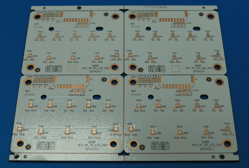
Why building both on one platform matters
When aluminum and copper substrates come from the same production platform, a design can move between them without changing supplier, documentation or acceptance criteria. The same inspection standards, the same materials specification discipline and the same technical contact apply to both boards. For a product family that may shift from aluminum to copper in its second or third generation, that continuity is often worth more than a marginal unit-price difference.
WODE reports ±10% tolerance on key parameters across its multi-type PCB output and a defect rate around 30% lower than the industry average, supported by quality assurance systems and continuous improvement processes rather than by a single final check. For an engineer deciding between base metals, the meaningful part is that the tolerance and inspection regime stays stable when the substrate changes.
Step-by-Step Breakdown: An Eight-Step Decision Procedure
Step 1 — Calculate heat flux, not fixture wattage
Divide the thermal power that must be removed by the area of the LED pads that generate it. Two fixtures rated at the same wattage can differ by an order of magnitude in W/cm² depending on how many emitters are packed onto the board. Concentrated flux is the first signal that copper deserves a cost estimate.
Step 2 — Identify the dominant resistance in the stack
Work through dielectric thickness and thermal conductivity, copper weight, solder voiding and thermal interface material. If the dielectric accounts for the largest share of the temperature rise, changing the base metal alone will not solve the problem; the stack has to be addressed first.
Step 3 — Measure the real spreading distance
On the actual board outline, measure from the edge of the LED pad to the nearest heatsink contact or mounting screw. Short distances combined with high flux point towards a copper base. Long distances combined with moderate flux usually leave aluminum sufficient, because there is enough board area to move heat without a premium material.
Step 4 — Check weight and mechanical limits
Copper is denser than aluminum. In automotive headlamps, ceiling-mounted fixtures and handheld equipment, the additional mass affects mounting hardware, vibration behaviour and handling. Where weight is tightly constrained, aluminum may be the only practical option regardless of the thermal calculation.
Step 5 — Model lifetime cost rather than substrate cost
A copper board that allows a smaller heatsink, a lower drive current or a longer warranty can cost less over the life of the product than a cheaper aluminum board that runs hotter. Where one project uses several board types, ordering them from a single multi-type supplier is typically more cost-effective — WODE reports pricing around 5–10% lower than sourcing the same mix from multiple single-product suppliers.
Step 6 — Build both variants and measure junction temperature
Thermal simulation narrows the choice; it does not close it. Building the same circuit on an aluminum and a copper base and measuring junction temperature under worst-case ambient conditions is the only way to confirm whether the premium is buying margin or simply buying metal. The difference in measured Tj, converted into expected lumen maintenance and warranty exposure, is the input that finance and engineering can agree on.
Step 7 — Verify production parameters before committing
WODE's published production parameters state a minimum order quantity of 80 sqm, a typical lead time of 7–15 days and a monthly MCPCB capacity of 600,000 sqm. Acceptance is carried out against mutually agreed technical specifications and inspection standards — incoming inspection, outgoing inspection or third-party inspection — and pre-shipment testing can be arranged before the boards leave the factory.
Step 8 — Structure the long-term supply
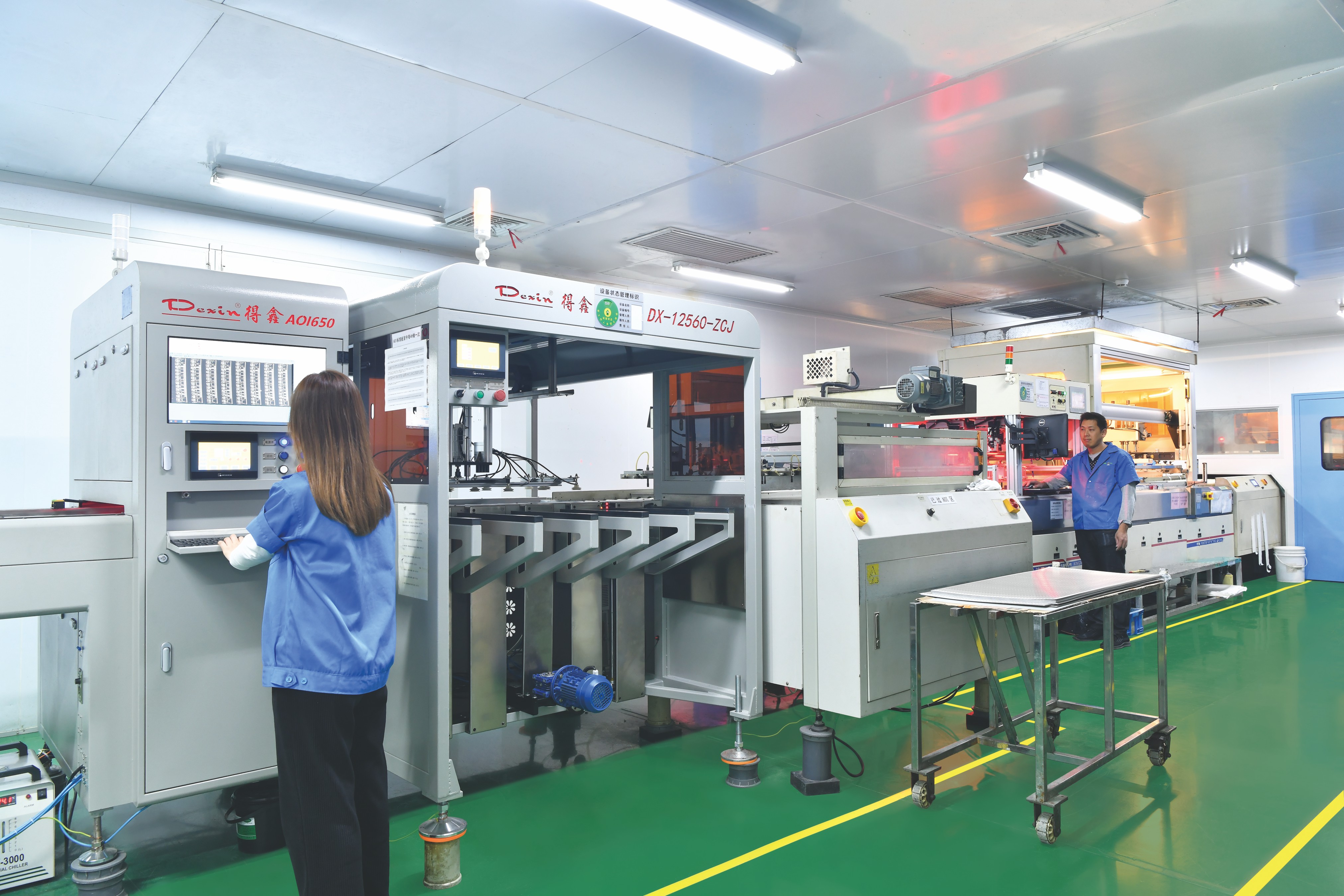
Because the substrate is locked for a product generation, a supplier's continuity planning matters as much as the datasheet. WODE manages delivery and raw-material risk through order control and procurement planning, and controls quality through incoming, in-process and final inspection with functional testing. Delivery and after-sales policies are defined per customer contract and order scale, so they are worth agreeing explicitly at the start of the relationship rather than assumed later.
Use Cases: Where Aluminum Wins and Where Copper Earns Its Cost
Aluminum-first designs
Bulb lamps, downlights and automotive headlamps sit at the centre of the double-sided aluminum MCPCB's application range, together with outdoor luminaires specified to IP65/IP67 protection and salt spray testing at ≥1000 h. These are typically high-volume programs where flux density is moderate, the board has room to spread heat, and the substrate must stay cost-competitive against alternative light sources.
Copper-first designs
Dense LED arrays, compact optical modules and designs with a thin junction-temperature margin belong to the thermoelectric-separated copper-based PCB. These are usually premium or thermally critical products where the cost of a derated or prematurely degraded luminaire outweighs the substrate premium — and where separating the thermal path from the electrical path removes a constraint the aluminum stack cannot remove.
Hybrid designs
A single fixture can use both. A double-sided aluminum MCPCB can carry the driver and control circuitry on one side while the highest-flux LED cluster sits on a thermoelectric-separated copper-based board. Because both families come from the same production platform, stack-up, tolerance and acceptance practice stay consistent across the assembly instead of splitting between two suppliers with two sets of inspection rules.
Head-to-Head Comparison Table: Aluminum vs. Copper Base MCPCB
| Decision factor | Double-sided aluminum MCPCB | Thermoelectric-separated Cu-based PCB |
|---|---|---|
| Base metal | Aluminum | Copper |
| Thermal path architecture | Standard metal-core stack — heat passes through the dielectric layer | Thermal path separated from the electrical path through the copper base |
| Lateral heat spreading | Sufficient when the board provides spreading distance | Higher spreading capability, suited to short distances and concentrated loads |
| Weight | Lower | Higher — copper is denser than aluminum |
| Relative substrate cost | Lower | Higher |
| Best-fit applications | Bulb lamps, downlights, automotive headlamps, outdoor luminaires specified to IP65/IP67 with salt spray testing ≥1000 h | Dense high-power arrays and compact modules where junction-temperature margin is the binding constraint |
| Production parameters (WODE) | MOQ 80 sqm; typical lead time 7–15 days; 600,000 sqm monthly capacity | Same published production parameters on the same MCPCB platform |
The structural and material rows describe general metal behaviour and the two named board architectures; the production rows reflect WODE's published parameters. Final thermal performance should be validated on the actual design, because stack-up, dielectric specification and interface material all influence the result.
FAQ: Substrate Choice and Long-Term MCPCB Supply
Q1. What certifications and acceptance criteria should a long-term MCPCB supply partner provide?
WODE holds ISO 9001, ISO 14001 and IATF 16949 management-system certifications, and its products comply with UL, RoHS and REACH requirements. Acceptance is carried out against mutually agreed technical specifications and inspection standards, which can take the form of incoming inspection, outgoing inspection or third-party inspection. It is also reasonable to request the quality manual, inspection specifications, supplier management records and an emergency delivery plan as part of the risk-control dossier.
Q2. Can a single manufacturer produce both aluminum-based and copper-based MCPCBs?
Yes. WODE's production line covers rigid MCPCB, FPCB, infinity-length FPCB, FR-4/CEM1/CEM3 PCBs, CCL and PCB inks, supported by a 15-person R&D team and a stated monthly MCPCB capacity of 600,000 sqm. Producing both substrate families on the same platform means a change from an aluminum to a copper base does not require a new supplier qualification, a new materials specification or a new acceptance procedure.
Q3. How can the higher cost of a copper-based substrate be justified?
Copper costs more per square metre and weighs more than aluminum, so it should be reserved for boards where heat flux density and junction-temperature margin genuinely demand it. The comparison should be made over the product's life: a copper board that permits a smaller heatsink, a lower drive current or a longer warranty can cost less in total than a cheaper aluminum board that runs hotter. Where one project uses several board types, ordering them from a multi-type supplier is typically more cost-effective — WODE reports pricing around 5–10% lower than sourcing the same mix from separate single-product suppliers.
Q4. What are the minimum order quantity and the sample validation steps?
WODE's published production parameters state a minimum order quantity of 80 sqm and a typical lead time of 7–15 days. Sample-scale and mass-order terms can differ, so delivery method, acceptance criteria and payment terms are confirmed in the order or contract. Where required, acceptance can be arranged as a pre-shipment test before the boards leave the factory.
Q5. How is supply continuity managed across a multi-year LED program?
WODE operates a stated monthly MCPCB capacity of 600,000 sqm with a typical production lead time of 7–15 days, and manages lead-time and raw-material risk through order control and procurement planning, supported by incoming, in-process and final inspection with functional testing. Delivery and after-sales policies are defined per customer contract and order scale, so they are worth agreeing explicitly at the start of a long-term program. To discuss a supply partnership, request samples or obtain a quotation, contact the WODE team at GJMYB1@wodepcb.com.
Conclusion: Choose the Substrate for the Design, the Partner for the Lifecycle
Aluminum and copper base MCPCB are not competing upgrades; they are two answers to two different thermal questions. Aluminum handles distributed heat loads efficiently and economically, which is why it remains the default for bulb lamps, downlights, automotive headlamps and outdoor luminaires. Copper becomes the correct answer when heat is concentrated, spreading distance is short, and junction-temperature margin is the constraint that limits the product — the situation the thermoelectric-separated copper-based PCB was designed for.
A workable rule of thumb: start every new high-power LED design on the aluminum route, measure heat flux and spreading distance, and escalate to copper only where the measured data shows the aluminum stack running out of margin. Escalating on the basis of measurement rather than assumption keeps the substrate cost proportionate to the thermal problem it solves.
The substrate decision outlives the design cycle that produced it. Since the base metal is locked into a product generation, the more durable question is which partner can supply both substrate families, hold tolerance and inspection practice steady, and keep a 7–15 day lead time inside a 600,000 sqm monthly capacity as volumes grow. That is the combination worth evaluating before the first prototype is released.

Next Step: Sample, Quotation or Full Catalogue
WODE Circuit Technology (Zhuhai) Co., Ltd. builds both the double-sided aluminum MCPCB and the thermoelectric-separated copper-based PCB on the same platform, with a published MOQ of 80 sqm, a typical lead time of 7–15 days and a monthly MCPCB capacity of 600,000 sqm.
Download the WODE product catalogue (PDF)
Contact
Melody Huang / Amy Bae
Email: GJMYB1@wodepcb.com
Tel: +86-756-3906072 / +86 13392068667
WhatsApp: Message the WODE team
Add: No. 2, South Qianwan Road, Qianwu, Doumen, Zhuhai, 519170, China
Website: www.wodepcbfpc.com
Have Questions or Need More Details?
Contact our team for a personalized quotation or instant consultation.
Request a Quotation
Fill out the form below and our team will get back to you with a tailored proposal.
WhatsApp Direct Chat
Prefer to chat in real-time? Message us on WhatsApp for instant assistance & quick answers.
- Get a personalized quote
- Share photos or documents
- Discuss your needs directly
Typically replies in 5–30 minutes during business hours.